Pinch Analysis for Heat Recovery Explained
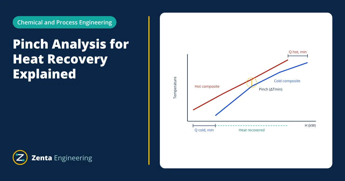
Pinch analysis is a method for designing heat recovery in a process. Hot streams that need cooling and cold streams that need heating are combined into composite curves. Where the curves come closest, separated by the minimum approach temperature ΔTmin, is the pinch. The method gives the minimum hot and cold utility the process can possibly use before any equipment is designed, and three rules show how to achieve it: no heat transfer across the pinch, no hot utility below it and no cold utility above it.
Most process plants heat some streams and cool others. Using steam to heat a feed while using cooling water to cool a product at a similar temperature wastes energy and money. Pinch analysis, developed by Bodo Linnhoff and colleagues in the late 1970s, gives a systematic way to find how much heat can be recovered between process streams, and sets energy targets that designers can aim for. It has saved large amounts of energy in refineries, chemical plants, food processing and paper mills.
Basic data: hot and cold streams
The analysis starts from the heat and material balance. Each stream that changes temperature is listed with:
- Supply temperature (where it starts) and target temperature (where it must end).
- Heat capacity flow rate CP = mass flow × specific heat, in kW/K. The heat load is CP × ΔT.
Hot streams must be cooled; cold streams must be heated. Hot utility (steam, fired heaters) and cold utility (cooling water, refrigeration) supply what heat recovery cannot.
Composite curves and the pinch
All hot streams are combined into a single hot composite curve on a temperature versus enthalpy (heat load) plot, by adding their CP values over each temperature interval. The same is done for the cold streams. The cold composite is then slid horizontally until, at its closest point, it is exactly ΔTmin below the hot composite.
The plot shows three targets at a glance:
- The horizontal overlap is the maximum heat that can be recovered between process streams.
- The part of the cold composite that extends beyond the hot composite at the top is the minimum hot utility, QH,min.
- The part of the hot composite that extends beyond the cold composite at the bottom is the minimum cold utility, QC,min.
A larger ΔTmin moves the curves apart, raising both utility targets but needing less exchanger area. A smaller ΔTmin saves energy at the cost of more area. The best value minimises total cost.
The problem table method
Composite curves are good for insight, but targets are calculated numerically with the problem table algorithm:
- Shift temperatures: subtract ΔTmin/2 from hot stream temperatures and add ΔTmin/2 to cold stream temperatures, so that any feasible heat transfer becomes possible on a single shifted scale.
- Form intervals between all the shifted supply and target temperatures.
- Calculate the surplus or deficit in each interval: (ΣCP of hot streams − ΣCP of cold streams) × interval width.
- Cascade the heat from the hottest interval downwards, assuming zero hot utility at the top.
- Find the largest negative value in the cascade. Adding that amount as hot utility at the top makes every value zero or positive. That amount is QH,min, the bottom of the cascade is QC,min, and the point where the cascade reaches zero is the pinch.
- Given
- Four streams with ΔTmin = 10 K. Hot H1: 180 to 60 °C, CP 2 kW/K. Hot H2: 150 to 30 °C, CP 4 kW/K. Cold C1: 20 to 135 °C, CP 3 kW/K. Cold C2: 80 to 140 °C, CP 5 kW/K.
- Find
- Minimum hot and cold utility and the pinch temperature.
- Assumptions
- Constant CP; no phase change; single ΔTmin for all matches.
- Solution
- Shifted temperatures: H1 175 to 55, H2 145 to 25, C1 25 to 140, C2 85 to 145
Intervals and net surplus (hot CP − cold CP) × ΔT: 175 to 145: 2 × 30 = +60; 145 to 140: 1 × 5 = +5; 140 to 85: −2 × 55 = −110; 85 to 55: 3 × 30 = +90; 55 to 25: 1 × 30 = +30
Cascade from zero: 60, 65, −45, 45, 75. Largest deficit −45, so QH,min = 45 kW
Corrected cascade: 45, 105, 110, 0, 90, 120, so QC,min = 120 kW and the pinch is at shifted 85 °C - Answer
- Minimum hot utility 45 kW, minimum cold utility 120 kW; pinch at 90 °C on the hot side and 80 °C on the cold side
- Limitations
- Without any heat recovery the process would need 645 kW of heating and 720 kW of cooling. The check QC,min − QH,min = 720 − 645 = 75 kW confirms the energy balance.
The three golden rules of pinch analysis
To achieve the minimum utility targets, a heat exchanger network must obey:
- Do not transfer heat across the pinch. Every kilowatt moved from above to below the pinch adds a kilowatt to both hot and cold utility.
- Do not use cold utility above the pinch. The region above the pinch is a heat sink; it needs only hot utility.
- Do not use hot utility below the pinch. The region below is a heat source; it needs only cold utility.
Designers then build the network starting at the pinch, where matches are most constrained, using rules on the number of streams and CP values to make feasible matches. Each match becomes an exchanger chosen from the available heat exchanger types.
Applications and extensions
- Heat exchanger network design for new plants and retrofits of existing plants.
- Placement of utilities: steam levels, furnaces, heat pumps (should work across the pinch) and heat engines (should not).
- Distillation integration: reboilers and condensers should be placed so that they do not cross the pinch; see the distillation column.
- Total site analysis: several plants sharing a steam system.
- Water and hydrogen pinch: the same targeting logic for minimum fresh water or hydrogen use.
Large plants such as the Haber-Bosch ammonia process are highly heat integrated in this way. Pinch analysis rests on the energy balance from the laws of thermodynamics, and reliable temperature measurement is needed to collect good stream data from operating plants.
Frequently asked questions
What is the pinch point?
The pinch is the point where the hot and cold composite curves come closest together, separated by exactly the minimum allowed temperature difference. It divides the process into a region above the pinch that needs only hot utility and a region below that needs only cold utility.
How is the minimum approach temperature chosen?
By trading energy cost against heat exchanger capital cost. A smaller value recovers more heat but needs much more exchanger area. Typical values depend on the industry and fluids, often in the range of about 10 to 40 K for many chemical and refinery processes and lower for refrigerated or low temperature processes.
Is pinch analysis only for heat exchangers?
It started with heat exchanger networks but the same ideas apply to placing heat engines and heat pumps, integrating distillation columns, total site utility systems and even water and hydrogen networks, where concentration takes the place of temperature.
References
- B. Linnhoff et al., A User Guide on Process Integration for the Efficient Use of Energy, IChemE
- I. C. Kemp, Pinch Analysis and Process Integration, 2nd ed., Butterworth-Heinemann
- R. Smith, Chemical Process Design and Integration, 2nd ed., Wiley
Get one engineering email a week
New articles, worked examples and study notes every week. Free, no spam, unsubscribe any time.

