Welding Defects: Causes and Remedies
Welding defects are imperfections in a weld, such as cracks, porosity, slag inclusions, lack of fusion, incomplete penetration and undercut, that exceed the limits of the applicable code. They come from poor joint preparation, contamination, wrong parameters or technique, and are prevented by correct procedures, clean consumables and inspection.
Welding defects reduce the strength, fatigue life and leak tightness of a joint. A weld that looks neat on the surface can still hide porosity or lack of fusion inside. This guide explains the main defect types, why they form, how to find them and how to remedy them, for arc welding processes such as SMAW, GMAW, GTAW and SAW described in types of welding processes.
How welding defects are classified
ISO 6520-1 classifies geometric imperfections in fusion welds into six groups, each with a reference number:
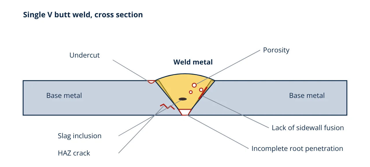
- Cracks (group 100): longitudinal, transverse, crater and HAZ cracks.
- Cavities (group 200): gas pores, wormholes and shrinkage cavities.
- Solid inclusions (group 300): slag, flux, oxide and tungsten inclusions.
- Lack of fusion and penetration (group 400).
- Imperfect shape and dimensions (group 500): undercut, excess reinforcement, overlap, misalignment, burn through.
- Miscellaneous (group 600): arc strikes, spatter, tarnish.
An imperfection becomes a defect only when it is larger than the limit allowed. ISO 5817 sets three quality levels for steel welds: B (stringent), C (intermediate) and D (moderate). The design or product standard chooses the level. AWS D1.1 gives its own visual and NDT acceptance criteria for structural steel.
Welding defects: causes, checks and remedies
| Defect | Likely causes | Check | Remedy |
|---|---|---|---|
| Porosity | Damp electrodes or flux, rust, oil, paint, draughts, wrong gas flow | RT, visual for surface pores | Dry consumables, clean joint, shield from wind, set gas flow |
| Slag inclusion | Poor slag removal between passes, deep narrow grooves, low current | RT, UT | Clean each pass, adjust bead placement and angle |
| Lack of fusion | Low heat input, fast travel, wrong torch angle, cold lap in GMAW | UT, RT, macro test | Raise current, slow travel, correct angle, open the groove |
| Incomplete penetration | Root gap too small, root face too large, low current | RT, back side visual | Correct joint fit up, back gouge and reweld |
| Undercut | Excess current or voltage, long arc, fast travel, wrong angle | Visual, gauge | Lower current, shorter arc, correct angle, blend or fill |
| Hot cracking | Sulphur and phosphorus, deep narrow bead, high restraint | Visual, PT, MT | Wider bead shape, cleaner filler, lower travel speed |
| Cold (hydrogen) cracking | Hydrogen, hard HAZ, residual stress, no preheat | MT, UT after delay | Low hydrogen process, preheat, controlled heat input |
| Distortion | Uneven heating, too much weld metal, poor sequence | Dimensional check | Balanced sequence, tack and clamp, less weld volume |
The NDT methods in the table (RT radiography, UT ultrasonic, MT magnetic particle, PT penetrant) are explained in NDT methods.
Cracks
Cracks are the most serious welding defects because their sharp tips concentrate stress and can grow under load, the mechanism behind fatigue failure.
- Hot (solidification) cracks form along the weld centreline while it is still partly liquid. Low melting films rich in sulphur and phosphorus, a deep narrow bead and high restraint promote them.
- Cold (hydrogen induced) cracks form after the weld has cooled, sometimes hours later, usually in the HAZ. They need three conditions together: diffusible hydrogen, a hard susceptible microstructure such as martensite, and tensile stress. Removing any one prevents them. This is why codes require a delay before final NDT on susceptible steels.
- Crater cracks form at the end of a bead if the arc is stopped abruptly. Filling the crater before breaking the arc avoids them.
- Lamellar tearing appears as stepped cracks parallel to the plate surface in T and corner joints, where shrinkage pulls on rolled plate through its thickness.
Porosity and inclusions
Gas pores form when gases dissolved in the molten pool, mainly hydrogen, nitrogen and carbon monoxide, come out of solution as the metal solidifies and become trapped. Sources include moisture in electrode coatings or flux, rust and oil on the joint, and air drawn into the arc when wind or a blocked nozzle disturbs the shielding gas.
Slag inclusions are pieces of non-metallic flux trapped between passes in SMAW, FCAW and SAW. In GTAW, touching the tungsten on the pool leaves tungsten inclusions, which show as bright spots on radiographs.
Fusion, penetration and profile defects
Lack of fusion means the weld metal did not melt into the bevel face or the previous pass. It is planar, hard to see and behaves like a crack. Incomplete root penetration leaves the root unfused, often from a tight root gap or thick root face.
Undercut is a groove melted into the base metal at the weld toe and left unfilled. It reduces section thickness and acts as a notch. Overlap is weld metal that flows onto the surface without fusing. Excess reinforcement and sharp toe angles also raise local stress. Spatter and arc strikes are surface imperfections; arc strikes can leave hard spots that crack.
Weldability equations behind cracking and fusion
Heat input controls fusion, cooling rate and HAZ hardness. EN 1011-1 defines it as:
where Q is heat input in kJ/mm, U arc voltage in V, I current in A, v travel speed in mm/min and k the thermal efficiency factor (0.8 for SMAW, GMAW and FCAW, 0.6 for GTAW, 1.0 for SAW). Too low a value risks lack of fusion and hard HAZ; too high a value lowers toughness and adds distortion.
Cold cracking risk is judged with the IIW carbon equivalent, used in EN 1011-2 to set preheat:
with element contents in weight percent. Higher CE means a harder HAZ. Steels with low CE, roughly up to 0.40, are generally easy to weld, while higher values need low hydrogen consumables and a preheat set from EN 1011-2. Steel grades are compared in types of steel.
- Given
- A 25 mm structural steel plate with C 0.18, Mn 1.40, Cr 0.10, Mo 0.03, V 0.01, Ni 0.10 and Cu 0.15 (weight percent). SMAW root and fill passes at 24 V, 140 A and 150 mm/min.
- Find
- The carbon equivalent and the heat input, and what they mean for cold cracking risk.
- Assumptions
- Thermal efficiency k = 0.8 for SMAW per EN 1011-1; composition from the mill certificate.
- Solution
- CE = 0.18 + 1.40 ÷ 6 + (0.10 + 0.03 + 0.01) ÷ 5 + (0.10 + 0.15) ÷ 15
CE = 0.18 + 0.233 + 0.028 + 0.017 = 0.458
Arc energy = 24 × 140 × 60 ÷ (1000 × 150) = 201 600 ÷ 150 000 = 1.344 kJ/mm
Q = 0.8 × 1.344 = 1.075 kJ/mm - Answer
- CE is about 0.46 and heat input about 1.08 kJ/mm. With CE above 0.40, use low hydrogen electrodes and determine preheat from EN 1011-2 for this thickness and heat input.
- Limitations
- CE is only an index. The actual preheat depends on combined thickness, hydrogen scale and restraint, and the final values must be qualified in the welding procedure.
Key formulas for welding defects
| Quantity | Formula | Symbols and units |
|---|---|---|
| Arc energy | E = U × I × 60 ÷ (1000 × v) | E in kJ/mm, U in V, I in A, v in mm/min |
| Heat input | Q = k × E | k = 0.8 (SMAW, GMAW, FCAW), 0.6 (GTAW), 1.0 (SAW) per EN 1011-1 |
| Carbon equivalent (IIW) | CE = C + Mn/6 + (Cr + Mo + V)/5 + (Ni + Cu)/15 | Element contents in weight percent |
Preventing welding defects
- Weld to a qualified welding procedure specification (WPS) with qualified welders, as required by AWS D1.1 or ASME Section IX.
- Prepare and fit up joints correctly: bevel angle, root gap, root face and alignment.
- Clean joints of rust, scale, oil, paint and moisture.
- Store and dry low hydrogen electrodes and fluxes as the manufacturer specifies.
- Protect the arc from wind and check gas flow and nozzle condition.
- Apply preheat and interpass temperature control where required; post weld treatments are covered in heat treatment of steel.
- Remove slag fully between passes and fill craters.
- Inspect visually during welding, then apply NDT at the extent the code requires. For repeated defects, a structured root cause analysis helps find the real source.
Repairs normally mean removing the defect by grinding or gouging, confirming removal with MT or PT, and rewelding to an approved repair procedure.
Safety
Grinding and gouging out defects produces sparks, noise and fumes. Use eye and face protection, hearing protection, fume extraction and fire watch. Radiographic testing uses ionising radiation and must only be done by licensed operators with controlled areas.
Welding defects interview and viva questions
- What three conditions cause hydrogen induced cold cracking? Diffusible hydrogen in the weld, a hard susceptible microstructure such as martensite in the HAZ, and tensile stress. Removing any one of them prevents the crack.
- Why is lack of fusion more serious than scattered porosity? Lack of fusion is a planar, crack like discontinuity with sharp edges, while pores are rounded and concentrate stress far less.
- What are the quality levels in ISO 5817? Level B is stringent, C is intermediate and D is moderate; the product or design standard selects the level.
- What causes undercut? Too high current or voltage, a long arc, fast travel or a wrong electrode angle, which melt the base metal at the toe without filling it.
- How does preheat reduce cracking? It slows the cooling rate, which lowers HAZ hardness and gives hydrogen more time to diffuse out of the weld.
Frequently asked questions
What is the most common welding defect?
Porosity is one of the most frequently found imperfections, because it comes from everyday problems such as damp consumables, rust, oil, paint or a disturbed shielding gas. Lack of fusion and slag inclusions are also common, especially in multi pass manual welds.
What is the difference between a weld imperfection and a weld defect?
An imperfection is any deviation from the ideal weld, as classified in ISO 6520-1. It becomes a defect only when it exceeds the acceptance limit set by the applicable code or quality level, such as ISO 5817 or AWS D1.1. Many small imperfections are acceptable.
Which welding defect is the most dangerous?
Cracks are treated as the most serious, because they are sharp, planar and can grow under fatigue or low temperature loading. Most codes do not accept cracks at all. Lack of fusion is also critical for the same reason: it acts like a crack inside the joint.
References
- ISO 6520-1:2007, Welding and allied processes, Classification of geometric imperfections in metallic materials, Part 1: Fusion welding
- ISO 5817:2023, Welding, Fusion-welded joints in steel, nickel, titanium and their alloys (beam welding excluded), Quality levels for imperfections
- AWS D1.1/D1.1M:2020, Structural Welding Code, Steel, American Welding Society
- EN 1011-1:2009, Welding, Recommendations for welding of metallic materials, Part 1: General guidance for arc welding
- EN 1011-2:2001, Welding, Recommendations for welding of metallic materials, Part 2: Arc welding of ferritic steels
- J. F. Lancaster, Metallurgy of Welding, 6th ed., Woodhead Publishing
- ASME Boiler and Pressure Vessel Code, Section IX: Welding, Brazing and Fusing Qualifications
Get one engineering email a week
New articles, worked examples and study notes every week. Free, no spam, unsubscribe any time.